3D Modelling & Laser Cutting
3d Modelling Introduction
For 3D modelling in Fusion 360 there are 3 main methods: Extrusion, Rotation and Sculpting. Extrusion is where you extend a 2D sketch profile into a 3rd plane. Rotation is where you rotate a 2D plane profile around an axis. Sculpting is where you start with a 3D object and by adding, removing, dividing, pulling and pushing the sections form a finished product.
Exercise: Lego Brick
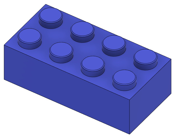
Let's build a Lego Brick! I'm sure you have played with Legos before so why not make them yourself. I would not be going too in depth for this exercise as I followed this video on How to 3D Model a Lego Brick by Product Design Online. You can also follow this tutorial if you are interested.
For this exercise I made use of functions like shell, extrude, pattern and fillet. My finished product is shown below, you can also find the file of what I did here.
Exercise: Cubes
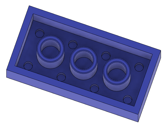
Make this object that made up of 20 cubes that are 20mm x 20mm x 20mm. This is then shelled to a thickness of 4mm. For this i used functions such as copy and paste, extrude, shell and combine. The file can be found here.
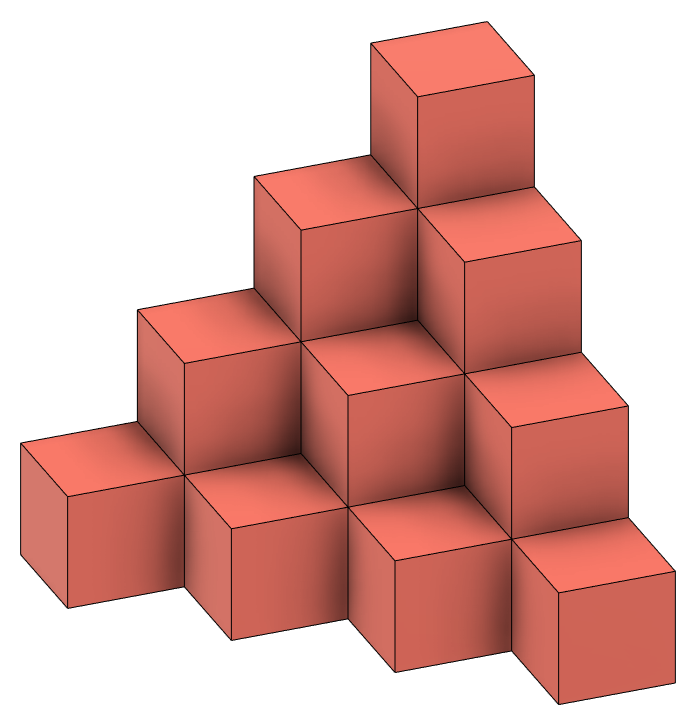
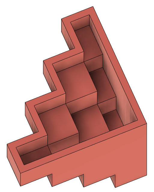
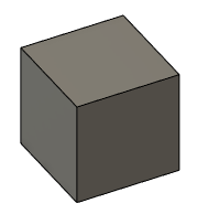
Well, how to create this? There are many methods but what did I use? I took a single cube, copy and pasted it 20 times until the shape was completed. I then combined all the cubes into one body. Next, I shelled the bottom to a thickness of 4mm. That completes this exercise.
Exercise: Mug with Handle
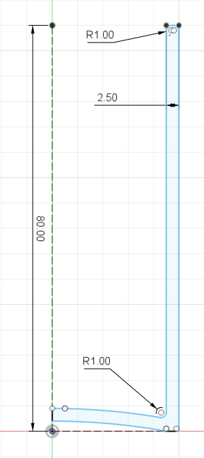
We are continuing our use of Fusion 360 by making a mug with a handle. The diamensions are 50mm(d) x 80mm(h). We needed to include an arc at the base of the mug and have the thickness be 2.5mm. Add a handle that is 6mm thick, for this it is free and easy.
To create this we first start with creating a sketch of how the main mug body should look like. This sketch profile is then revolved along the centre axis.
Next, create a new sketch on the same plane as the first and create a handle of your choice. A tip is to create the tips of the handle slightly into the revolved profile so that it is fully inside. For my handle I used the fit point spline function.
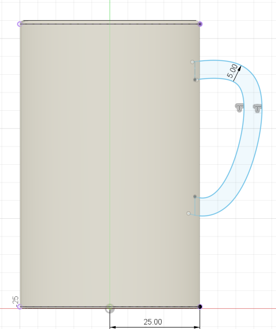
Extrude this handle bar symmetrically to a thickness of 6mm. And the mug is completed!
Exercise: Hex Nut
A hex nut? Yeah it can also be made by 3D modelling. For this I will go into slight details as I followed this video on How to 3D Model a Hex Nut
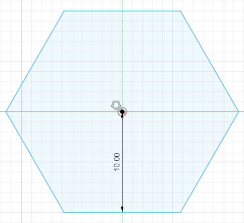
by Product Design Online. You can follow the tutorial if you are interested. This hex nut is 20mm between flat surfaces and 10mm thick.
First, a sketch of a pentagon. Then extrude it 10mm. Next, create a triangle as shown below and use the revolve function and cut away from the current body.
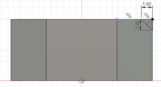
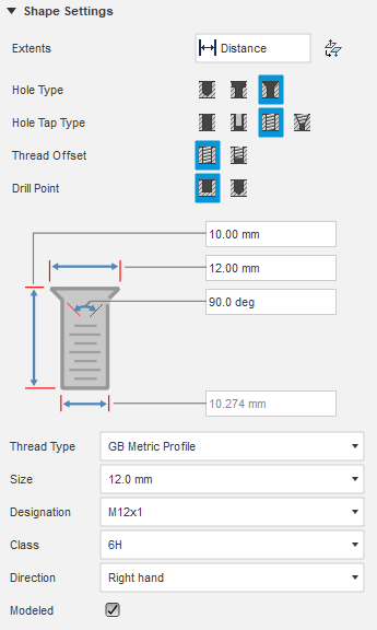
Once done create a plane in the middle of the nut and mirror the revolve cut profile. Now both sides should have this chamfer. Lastly, add the threaded hole and it is done.
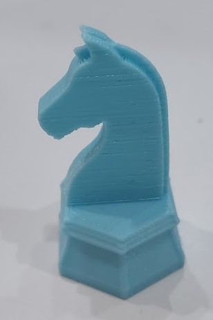
Assignment: Chess Piece - Knight
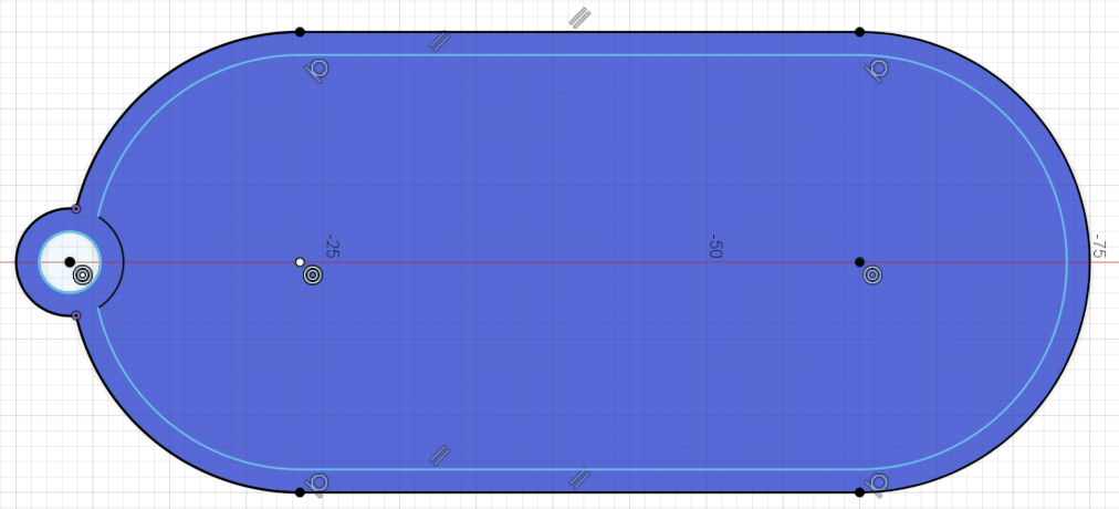
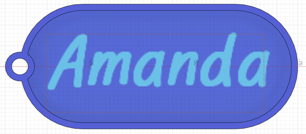
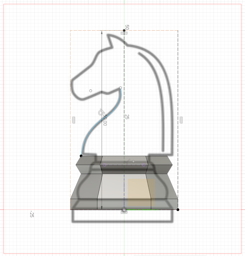
Using what was taught to far, design a knight chess piece that has a base of 30mm, height of 50mm, and head thickness of 5mm. The base should also be hollow. Using a template image as a canvas to help complete this exercise.
The template image I used is this knight chess piece template I took off the web. For this, I used functions such as extrude, loft, fillet and a few others. The curved lines can also be created using the line function.
Computer Controlled Cutting Introduction
For Computer Controlled Cutting, it works on a 2D profile which provides an outline of the cut. Vector file formats are needed to begin laser cutting, these are DXF (Data eXchange Format), PDF (Portable Document Format), SVG (Scalable Vector Graphics). For my assignments I would be using LibreCAD to produce my DXF files for printing.
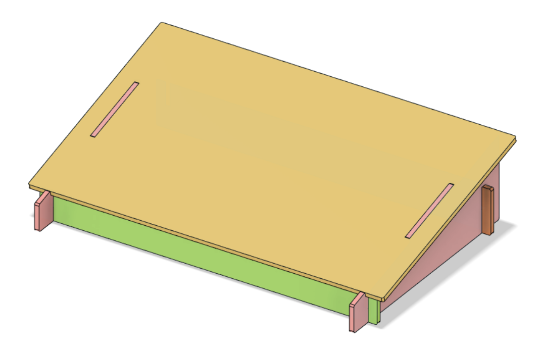
Exercise: Laptop Stand
Using Parameters in Fusion360 I made the laptop stand. The laptop stand also used other tools like combine and join to create. Using parameters make the editing process quicker especially if the thickness of the material is known.The file can be found here.
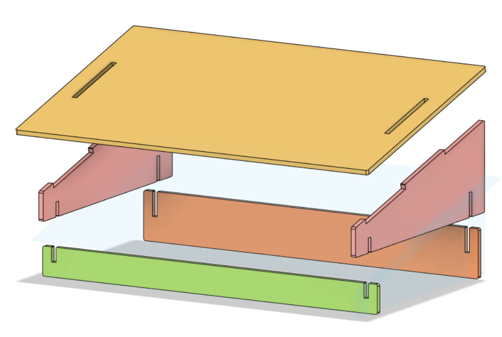
I created each coloured component then joined them such that intersecting parts were cut from the selected components.
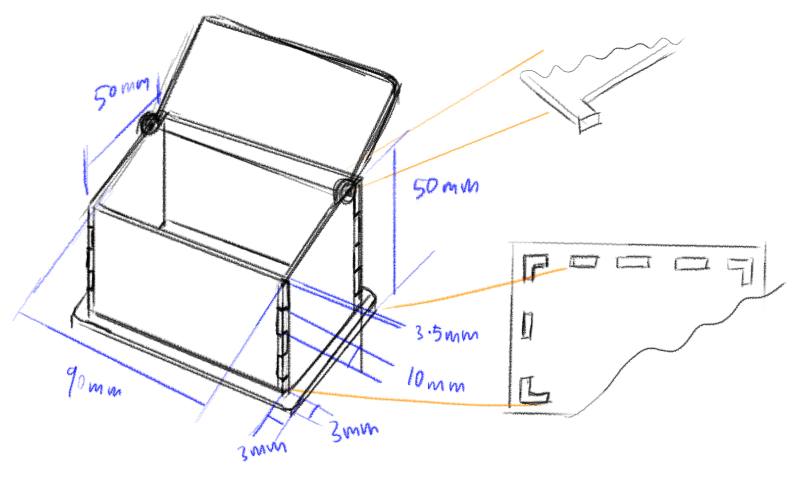
Assignment: Music Box
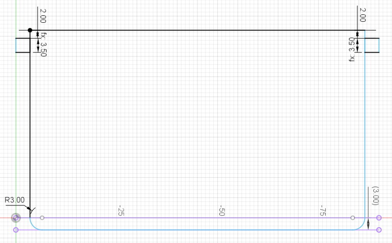
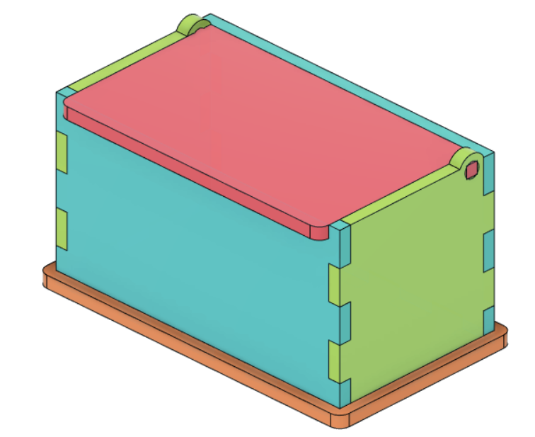
Using similar steps in creating the laptop stand, I created this paramatric laser cut box. First, I started with a sketch.
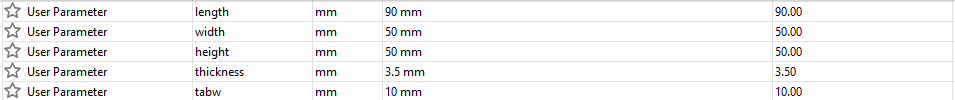
Then, I started using Fusion360 to model the box. Step 1, create the parameters used in this model.
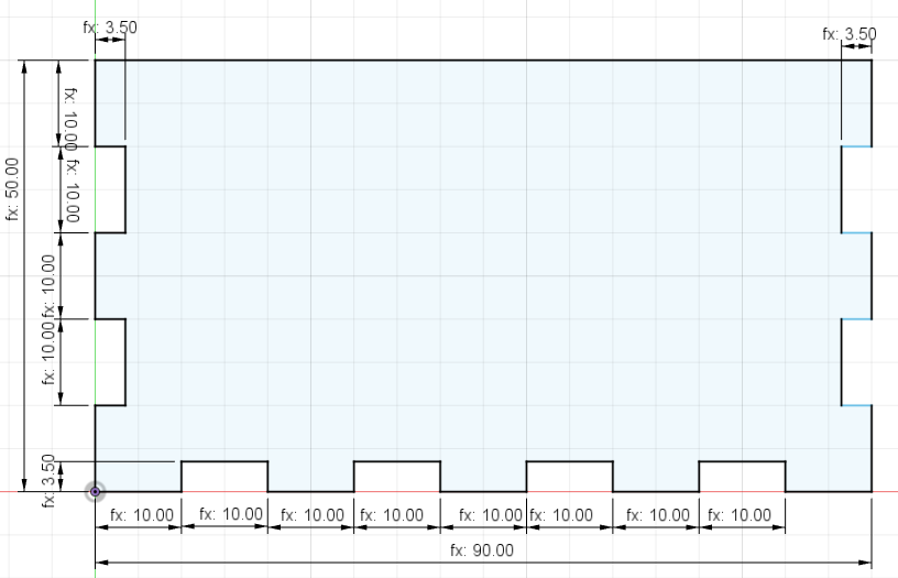
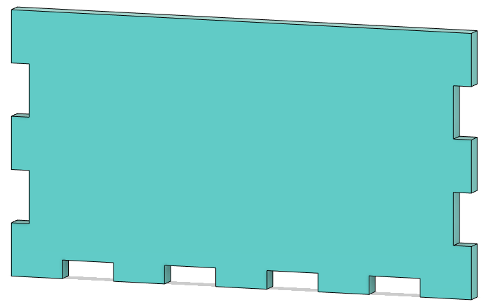
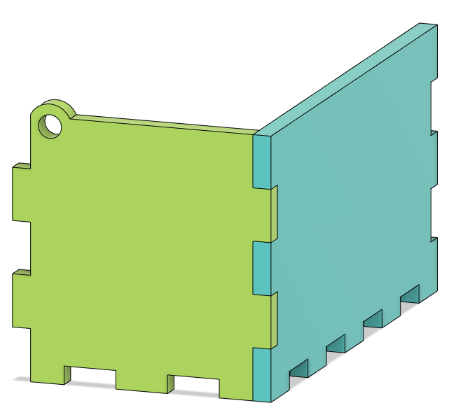
Step 2, I sketched out the first side using the 'tabw', 'height', 'length' and 'thickness' parameters. Then i extruded it to the 'thickness'. This forms the first side.
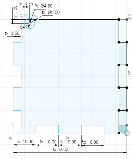
Step 3, I repeated step 2 and created the 2nd side. There is a hole created for the top lid to open and close.
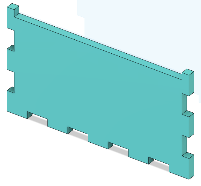
Step 4, I used the Mirror tool and mirrored the current objects on a plane I created at the halfway mark of each diamension. This gave me 4 different side pieces.
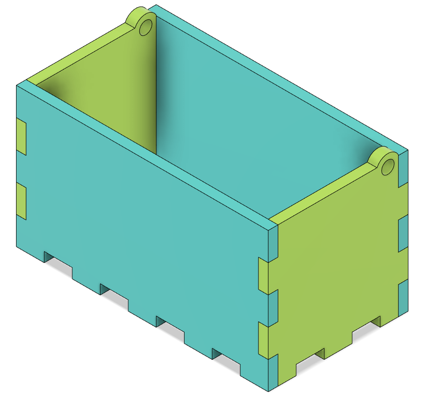
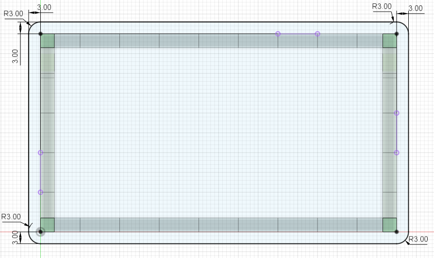
Step 5, I created the sketch of the bottom piece at 56 by 96 mm respectively. I extruded it to the 'thickness'. Next, I used the Combine tool and cut the 4 sides from the bottom piece. This gives the completed bottom piece with all the tab holes present.
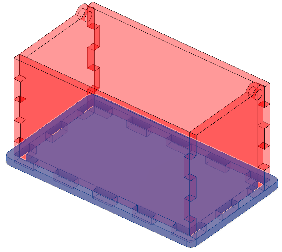
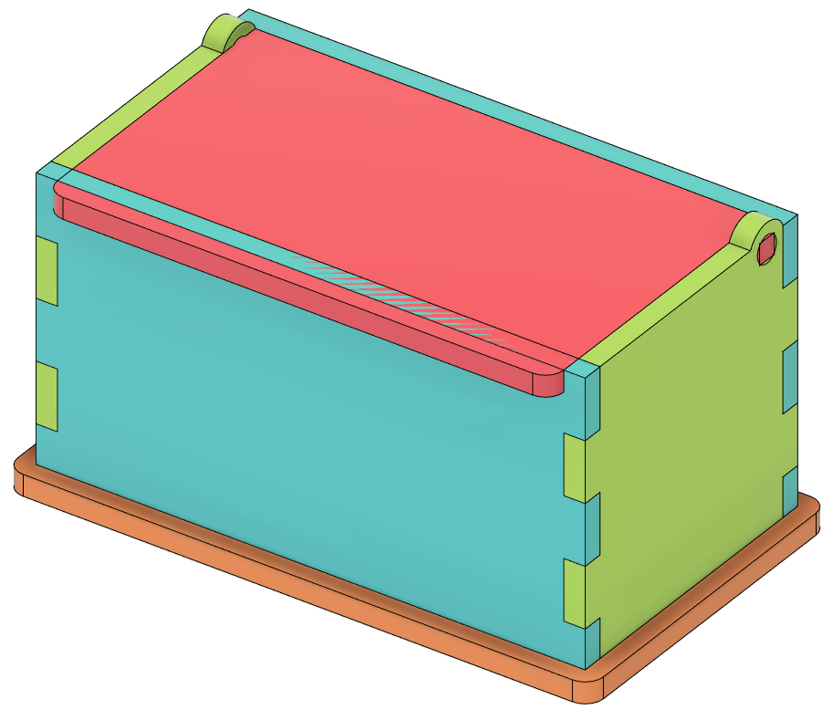
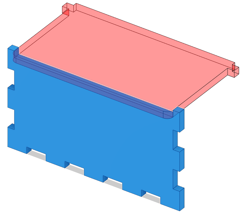
Step 6, I sketched the top piece with the tabs to hold the lid in the holes made on the 2nd side. I extruded it out to the 'thickness'. As seen below the extruded top has intercepted the front piece.
Step 7, we need to get rid of the part on the front side that is cutting into the top. Using the Combine tool I cut the top from the front piece and forming the new front piece as shown.
Now we are done with our model of the Music Box!
Laser Cutting
After the completion of the Music Box we went on to cut it with a laser machine. I first checked the parameters and diamensions of my design and making sure the thickness of the material is set correctly.In this case my material was plywood of 3.5mm.
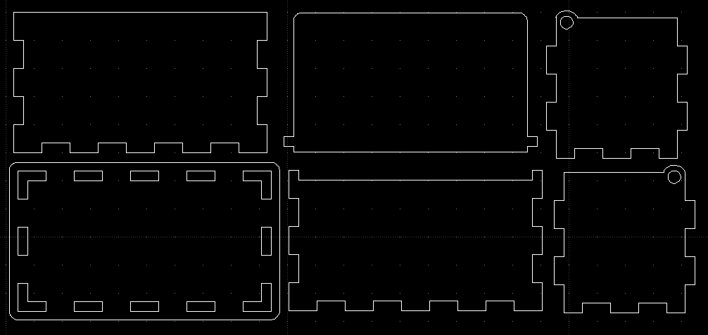
To prepare my piece to cut I exported my pieces to DXF files. In order to do this i had to select a sketch and click the "Save As DXF" function. I repeated this for each side. Next, I imported all these to LibraCAD and adjusted each piece to ensure minimal material waste. The DXF file can be found here.
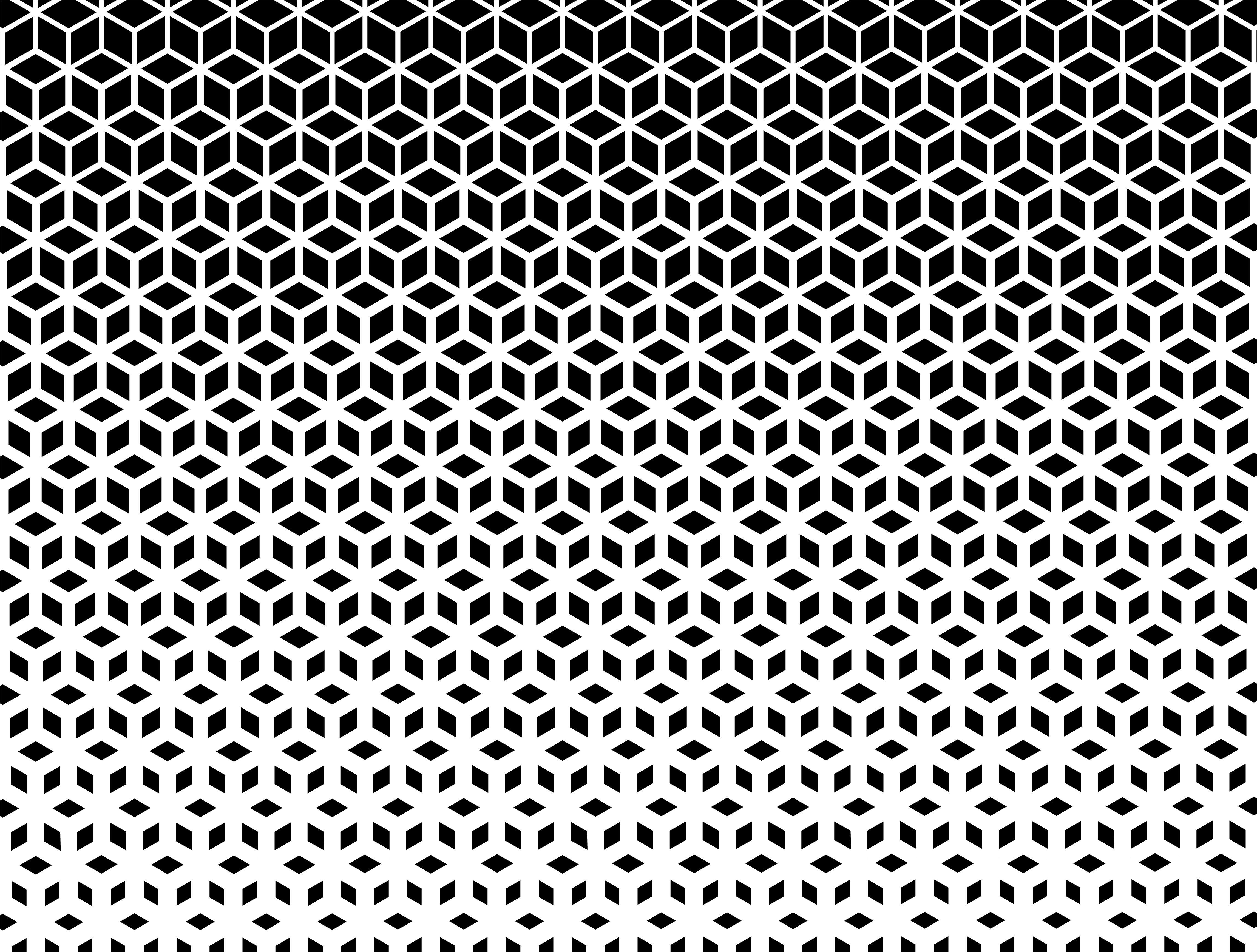
After exporting the DXF file from libreCAD, i imported this file to CorelDraw. CorelDraw is a graphic editor. I added in a design onto the front piece of the box, this would be engraved. Make sure the cut lines are set as hairline and the graphics for engrave.
Next, I sent this file to the machine. In this case the machine I used was Epilog Fusion Pro. I made sure the plywood was placed correctly in the machine. The cut settings were Speed: 25%, Power: 80%, Frequency: 50%. The Engrave setting were left as default. The thickness was set to 3.5mm.
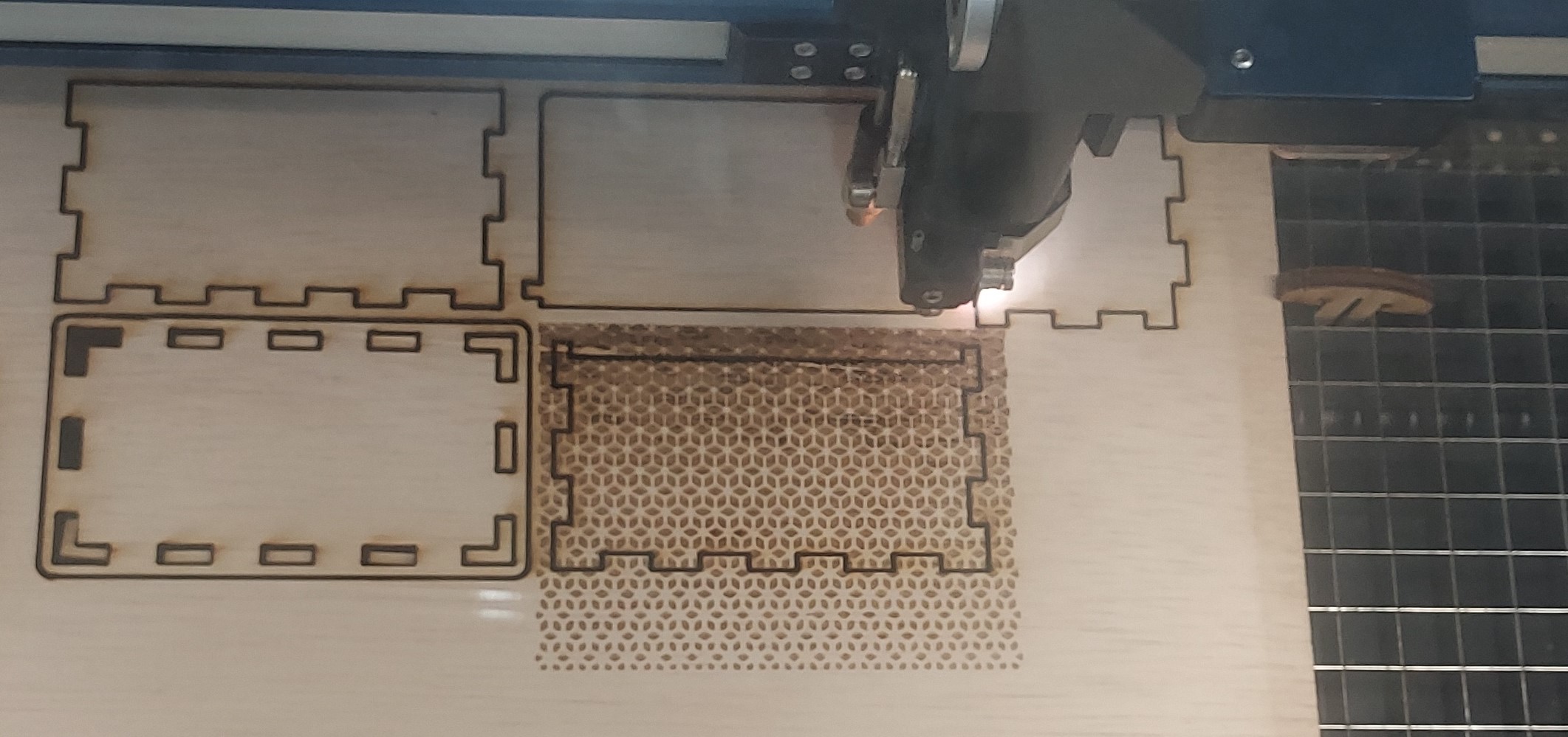
Laser Cutting in progress...
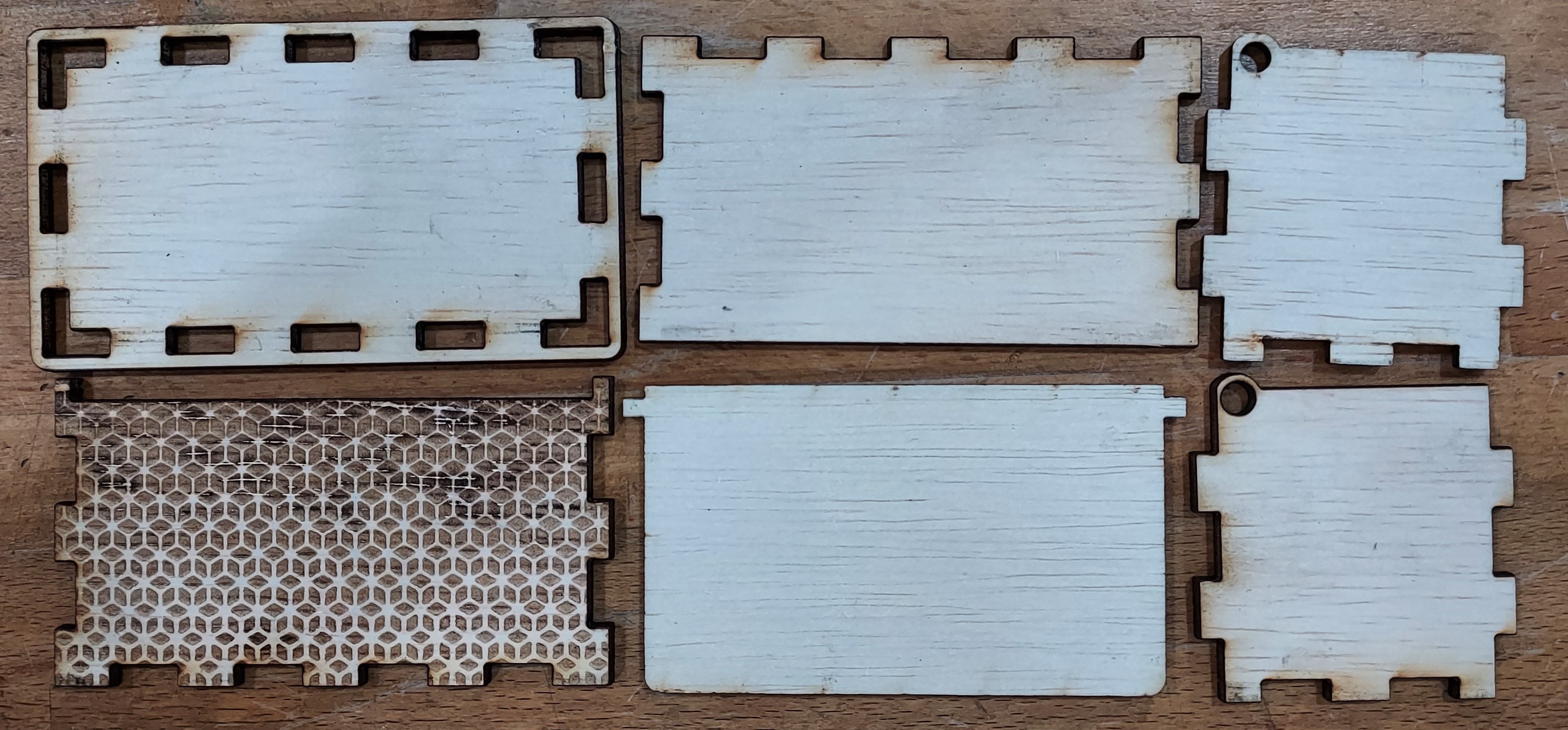
Laser Cut Pieces
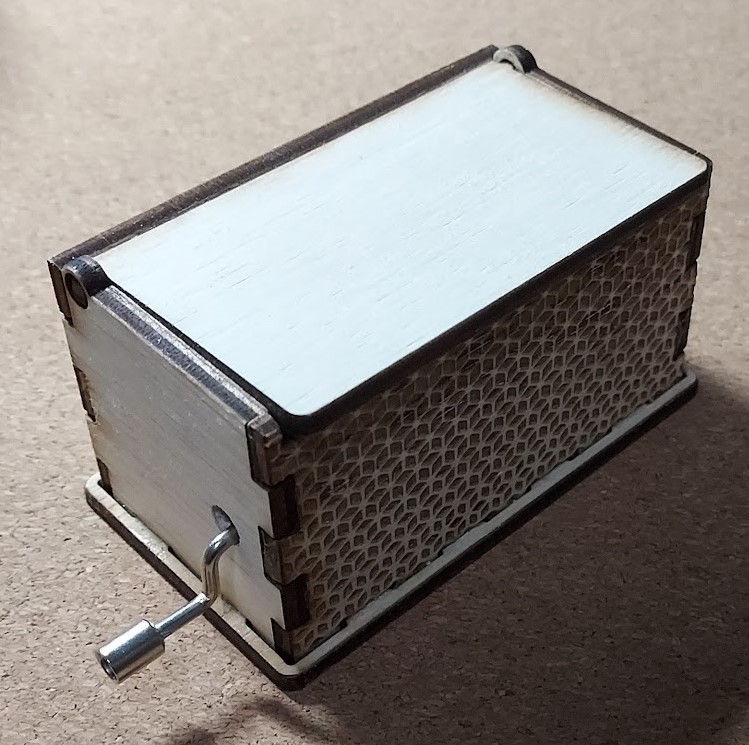
I then drilled a hole on the left side piece and started assembling. I used UHU glue to attach everything together. The finished project looked like this:
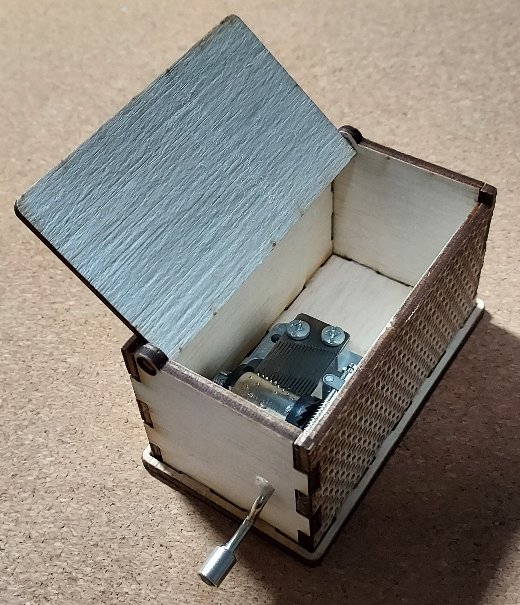
While trying to fix everything in place, I realised my design is not very suitable as I have to make sure the top and side pieces are already placed together and attach the bottom piece on. This was harder than expected due to the music player handle needing to be in the hole.
3D Printing
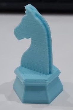
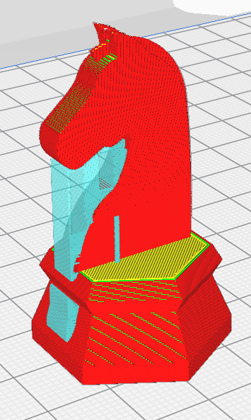
We printed the Knight Chess Piece on a Ultimaker 2+. To prepare the file for printing we have to export the Fusion360 file as an STL file. Next open the file in Ultimaker Cura and do the necessary settings needed. For me, I used 0.2mm Layer Height, 0.8mm Wall Thickness, 20% Infill, Zig Zag Support and no Build Plate Adhesion.Slicing the print should look something like this:
Export the file as g.code and save to an SD card and insert into the printer. It took about 40 minutes to print. The finish print looked like this: