Topics Covered
Introduction
Why make our own PCB?
It is to suit customised electronics to meet product requirements and also for better product integration.
For our PCB production we would be using Stepcraft 420. We would be fabricating a FTDI and UPDI board.
PCB G-Code
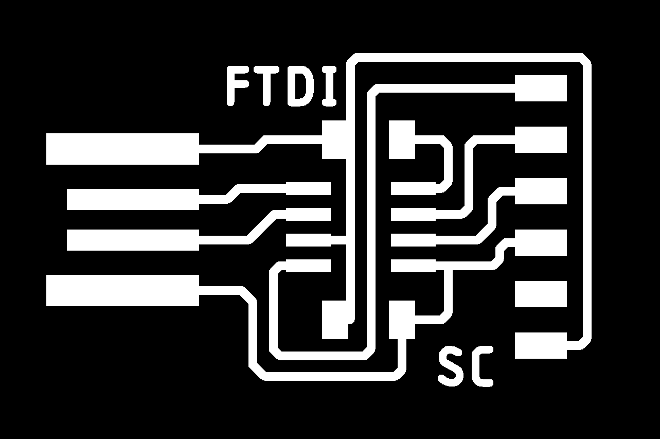
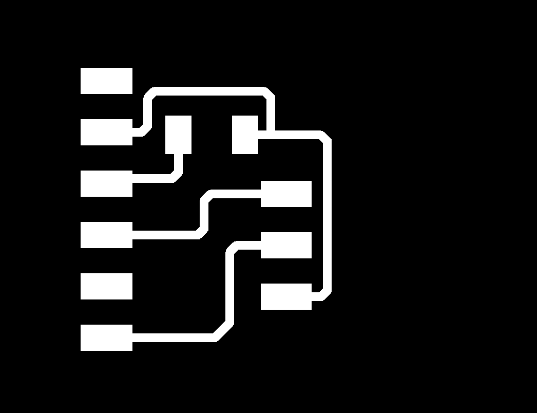
Before we can start machining our PCB we would first need to have a design ready. We are already given the the board traces and outline as shown below.
FDTI Board

UPDI Board

Next we head to mods community created by Mr Steven Chew.
Do the following: right click > Programs > Open Server Program > Mill 2D PCB png. You should see the following:
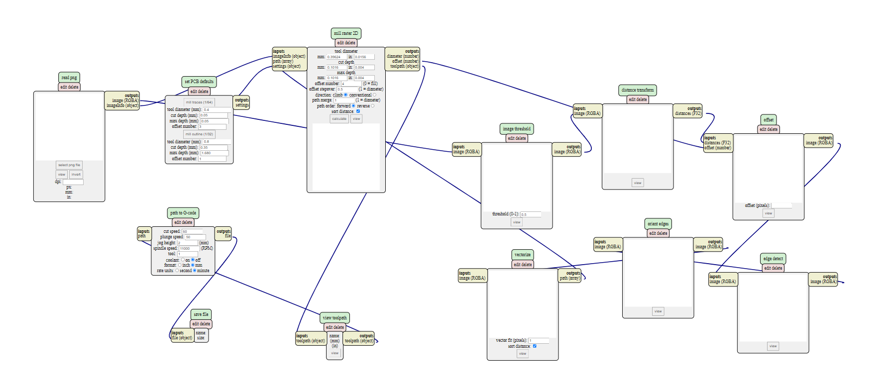
Step 1: Select "mill traces"
Step 2: Select the board's trace image file
Step 3: Select "calculate"
You should be shown the mill path as well as have a g-code file automatically downloaded.
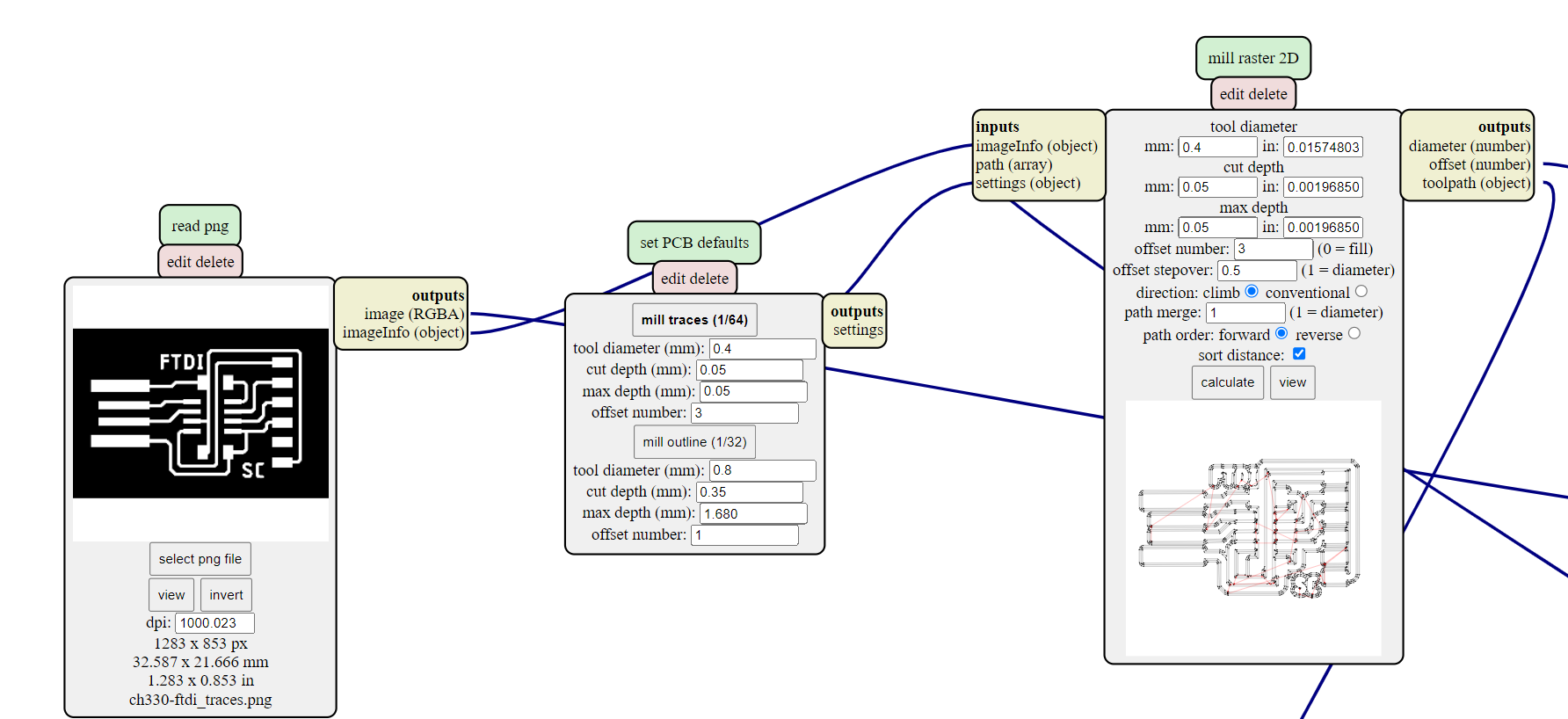
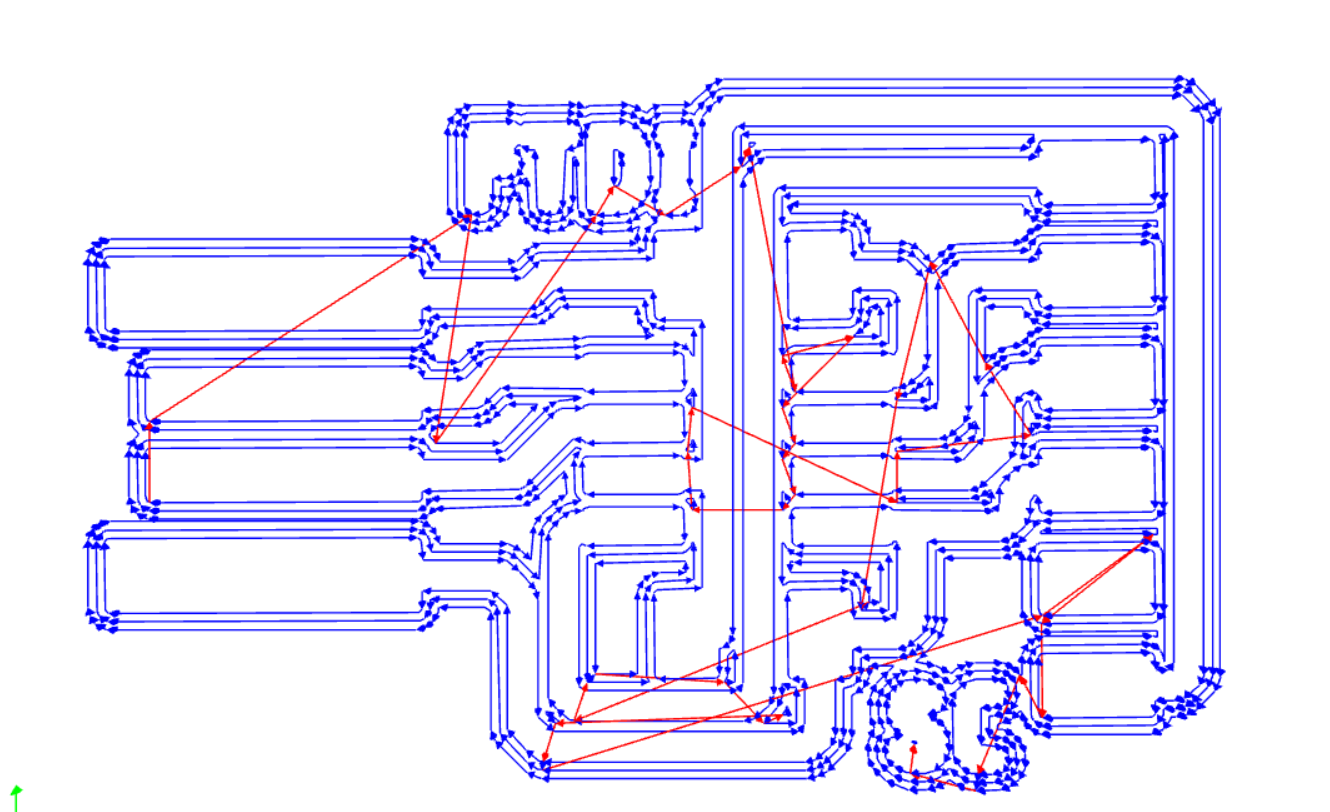
Repeat steps 1 to 3 for the board outline.
FTDI G-codes: outline | traces
UPDI G-codes: outline | traces
PCB Milling
Now we move on to milling. We will be using Stepcraft 420 in this module. First we need to set up the board we are going to cut.
Step 1: Stick double sided tape evenly onto the back of the board.
Step 2: Position the board on the machine bed.Ensure that the board is level and stuck well onto the machine bed.
Step 3: Put in the milling bit of choice and tighten well.
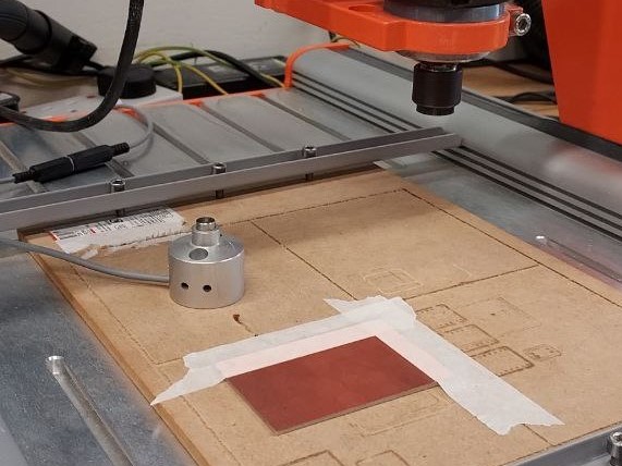
Next we have to calibrate the software before we can start running it. We will be using UCCNC software.
Step 4: Load the board's traces g-code file into the software.
Step 5: Set the machine's Z-axis zero using "purge". Be careful to centre the mill bit directly over the z-zero sensor.
Step 6: Move the mill head to the desired X-axis and Y-axis. Set the machine's X & Y-axis zero.
Step 7: Once everything is set, click "cycle start".
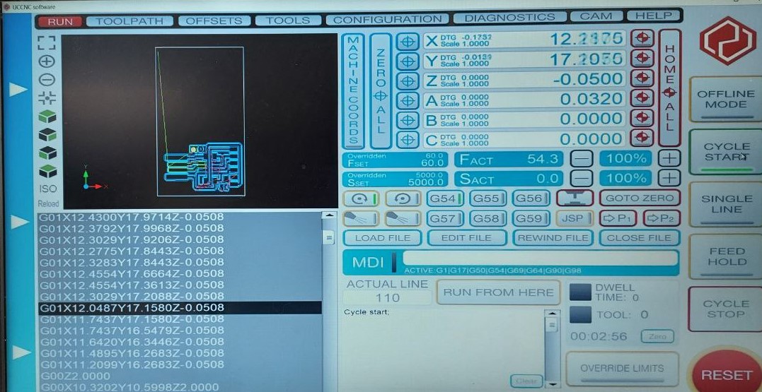
Our PCB milling has started! If you notice a build up of dust just use a vacuum or brush to get rid of it. Once the traces is completed, just repeat step 4 & 7 again for the outline.
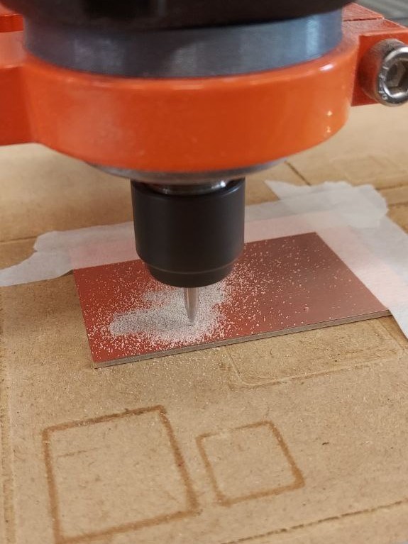
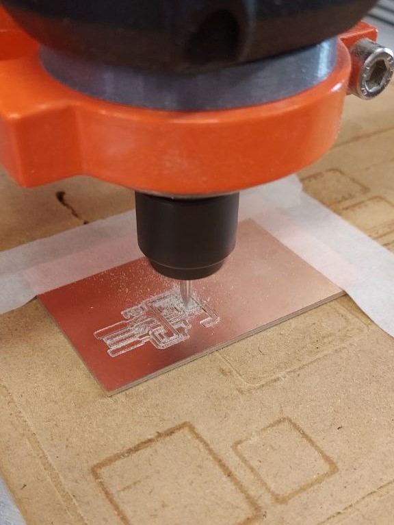
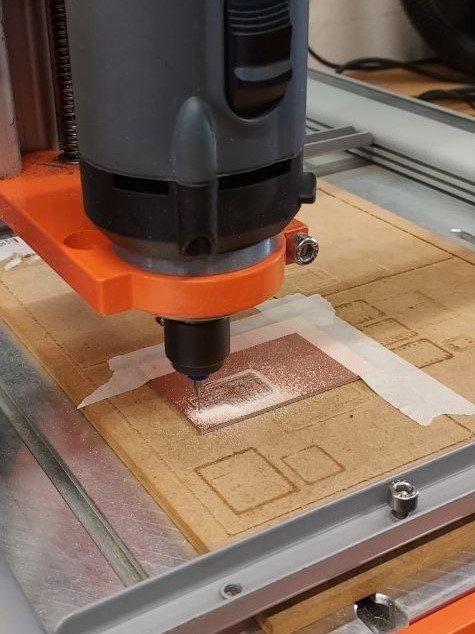
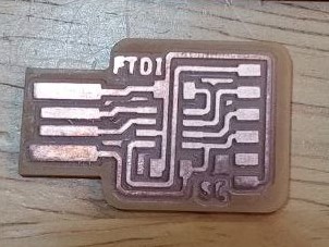
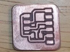
After milling is completed, there may be some burrs present. Just use some sand paper and sand them away! They should look like this after.
PCB Assembly
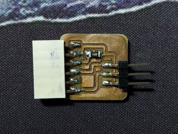
Now that we are done with fabricating our PCB boards, it's time to solder on the components. This would be much easier if you have a reference to refer to when you are soldering. This is how mine looks after I finished soldering!

