Introduction
We are going to be designing and creating a ATtiny412 hello-world board. We will be making use of the EAGLE software to design our board.
Creating the Schematic
Before we can create the board layout, we first must layout all of our components and figure out how to link all of them.
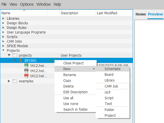
Step 1: Create a new project. Under that project create a new schematic.
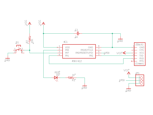
Step 2: Place all of components down.
Step 3: Link all of the components as you desire.
Creating the Board
After we are done with the schematic, we can start creating the board. It may look messy at first but with some adjusting it will look presentable.
Step 1: Create the board view from the schematic view.
Step 2: Move the components around until you are satisfied with the layout.
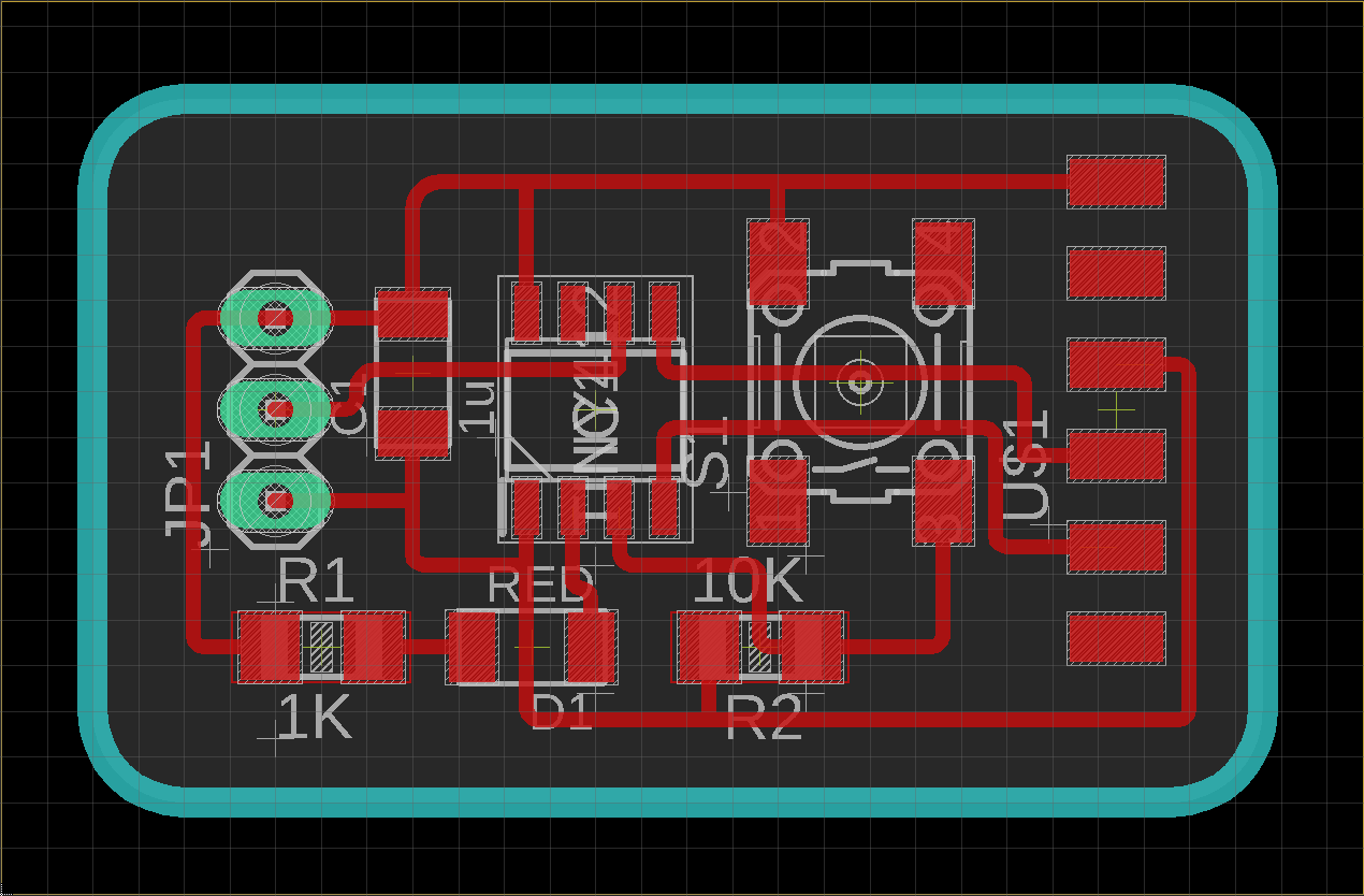
Step 3: Use "Route Airwire" and "Ripup" to connect the components as shown by the yellow lines. If some of the lines are not possible, go back to your schematic and readjust it.
Step 4: Create the borders for the board.
If everything is done correctly you should have something that looks like this.
Exporting Images
Once we are done adjusting our board layout, it's time to export. But before that, we need to prepare which layers we want to show in our image.
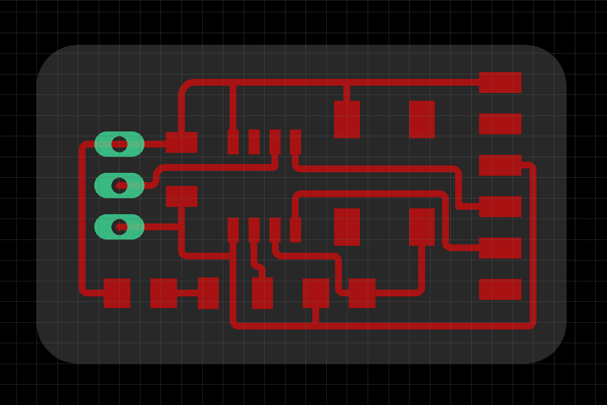
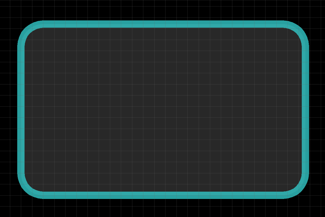
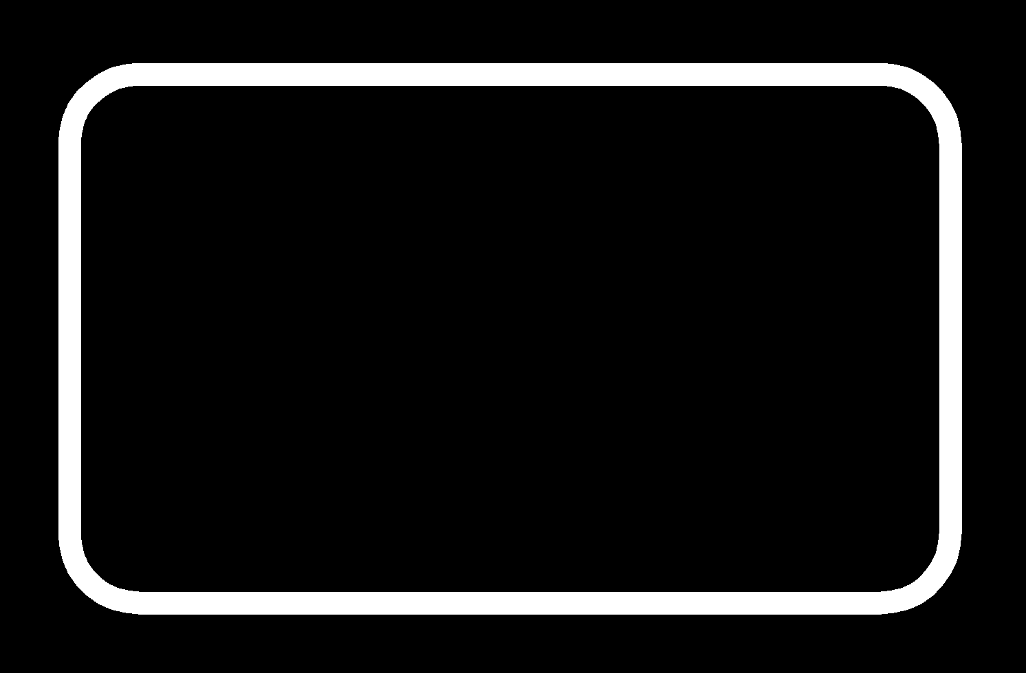
For the board traces, hide all layers but 1-Top & 17-Pads.(left) For the board outline, we hide all layers but 46-Milling.(right)
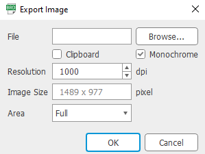
Use the following setting to export to image.
You should have something that looks like these.
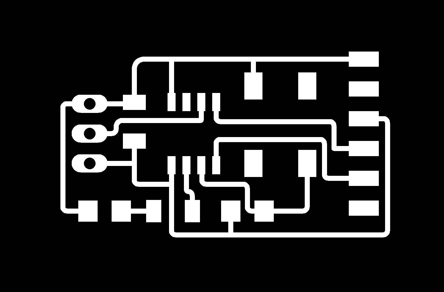
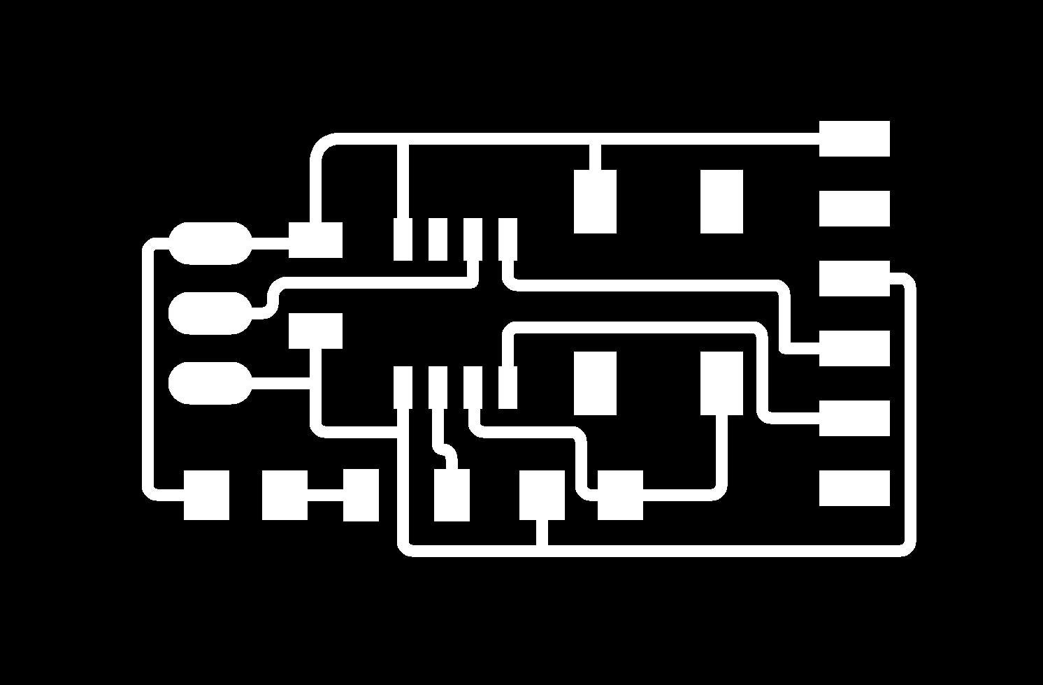
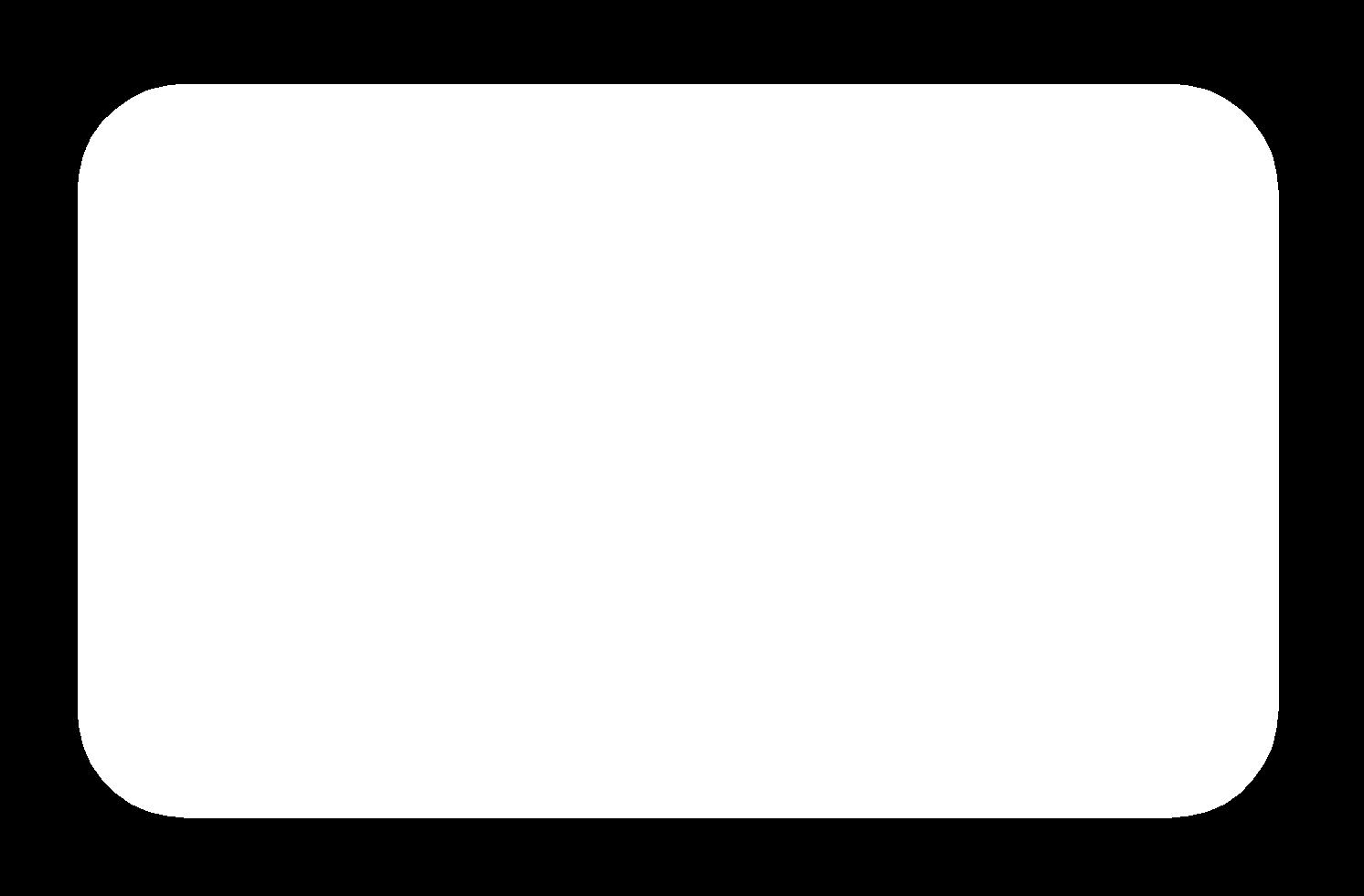
Notice that they have holes in them? These holes can be filled in using GIMP. Your result should be as follows.
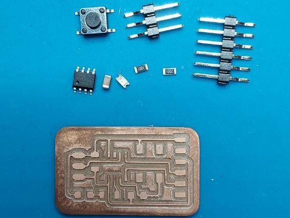
Production of Hello Board
We can now mill our hello-world board using Stepcraft 420. To know how to use it, click here.
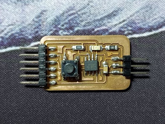
Once milling is done, we can now solder on the components. And we are DONE!